My very first Airsoft AEG was a Tokyo Marui G3-SG1. I got it more than a decade ago, and surprisingly I still have it, or what’s left of it anyway. It’s been some time since my work on a friend’s airsoft automatic electric gun (AEG), the TM MP5K-H v1.0, and I’ve been wanting to rebuild my G3 since.
Like any fresh build we need to consider the basics, and to that end I will be focusing on the piston assembly, a component which I consider a very important foundation to any AEG. The piston assembly is an internal component found in the gearbox shell that is in charge of transferring the spring’s energy to compress air used to launch plastic pellets/bbs as projectiles.
Looking back, I am surprised at what little attention I gave to this very important component when I first started my foray into airsoft tinkering. Work on the piston ensures smooth operation and directly improves the system’s longevity which are core aspects of reliability. So let’s move along and revisit the AEG piston and how to make this part right.
For those who are interested, I’ve taken the liberty of capturing the process through video in the following segment. However, I highly recommend you read through the rest of the entry as it covers more details and reasoning behind the actions.
Moving on, I’d say that a lot of work goes into tuning the piston assembly apart from dealing with compatibility, variations in design, and material composition. When combining these parts you have to keep in mind the intended application. For example, if you are going for more of a dedicated marksman’s rifle that uses semi-auto fire mostly, shaving down weight of the piston assembly may not be necessary. The opposite may be true for a build focused on extremely high rates of fire where a lightened assembly equates to more speed needed to keep up with the gears.
You also have to keep in mind that slapping on parts as they are may or may not work on stock AEGs, and that they may run poorly or cause damage over time. Special care and preparation needs to be taken to make sure parts mesh together cohesively.
Components and Function
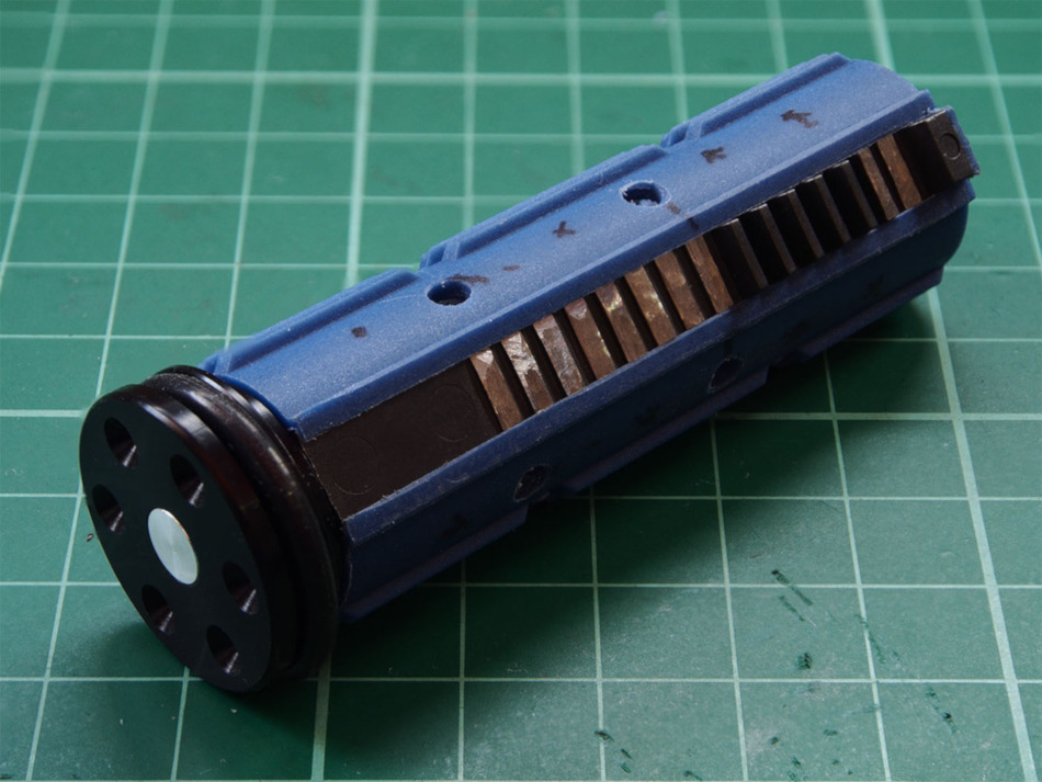
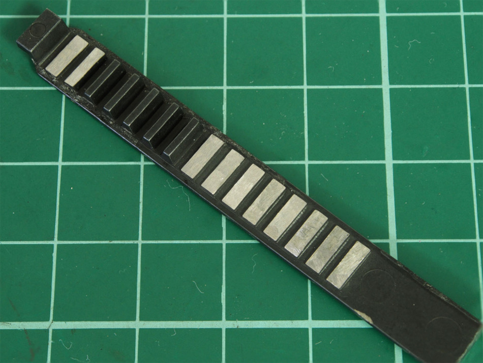
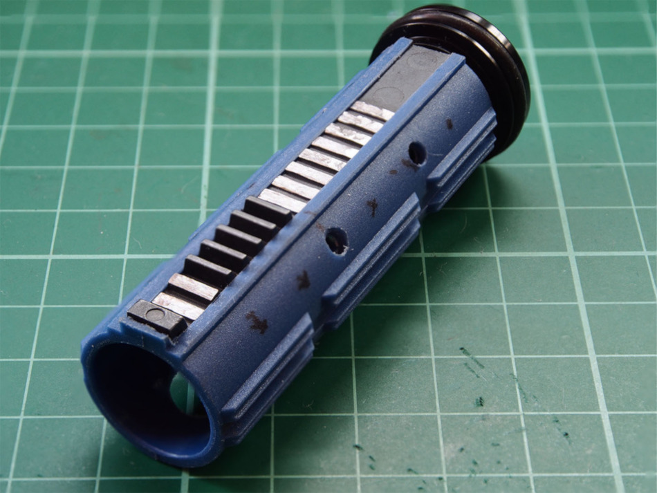
There are two main parts that make up the piston assembly, and they are the piston body and the piston head. The piston body has ridges called teeth which a sector gear (toothed gear) interfaces with to draw the piston back into the gearbox. Behind the piston body sits a spring which is compressed by this rearward motion.
After the sector gear travels the length of the piston’s teeth, the piston is released and sent flying forward by the spring’s stored energy thus initiating the compression cycle.
The piston head on the other hand has an o-ring on it that forms the seal on the cylinder walls in which the piston assembly travels through as it pushes air through the cylinder and cylinder head.
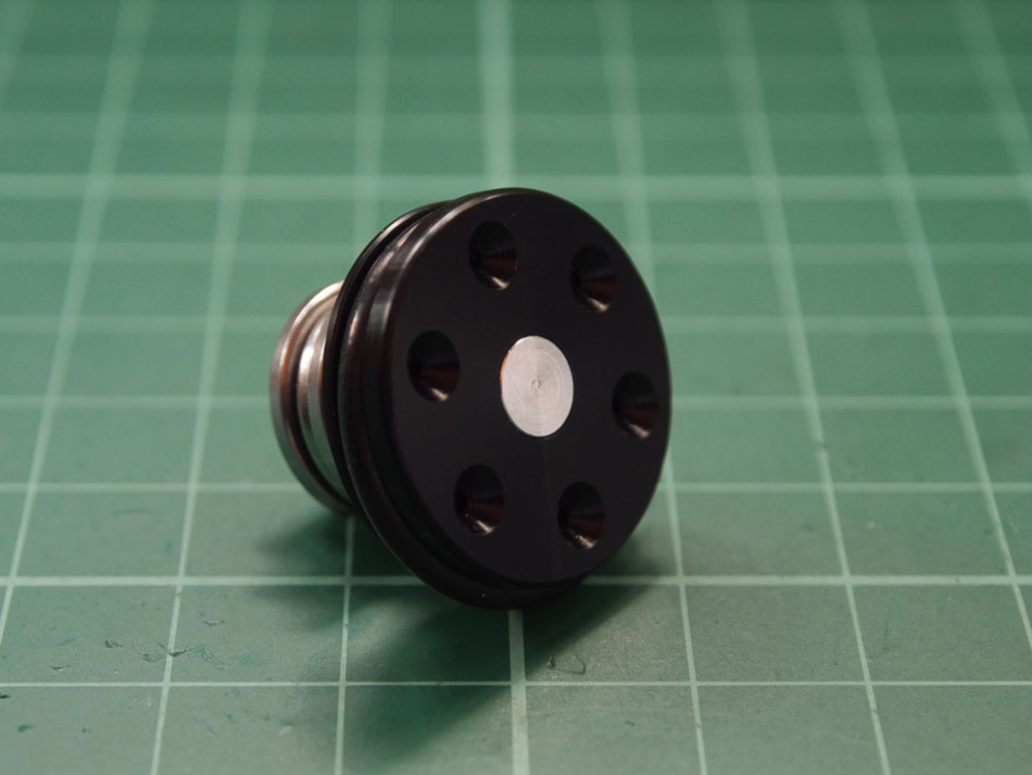
The piston head has holes on it’s face where air comes in as it is pushed forward to push against the o-ring on the cylinder walls. In addition, it was mentioned by another tech that these same ports serve a secondary function to let air pass back through when the piston is drawn back. You can check out more from him on his Instagram, @guntech762.
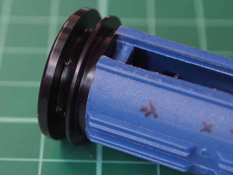
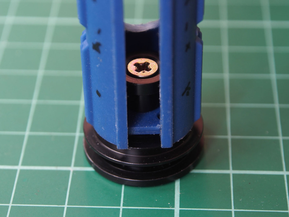
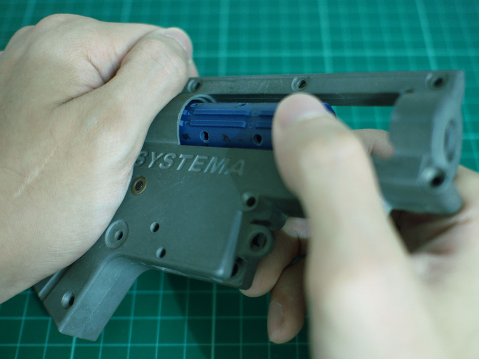
Here’s a breakdown of the piston head’s typical components. Below, you have the piston head itself, the o-ring seal, a thrust bearing, and the piston head retainer and retaining screw.
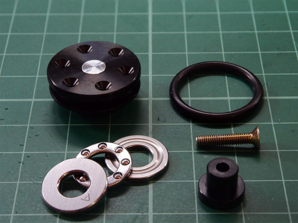
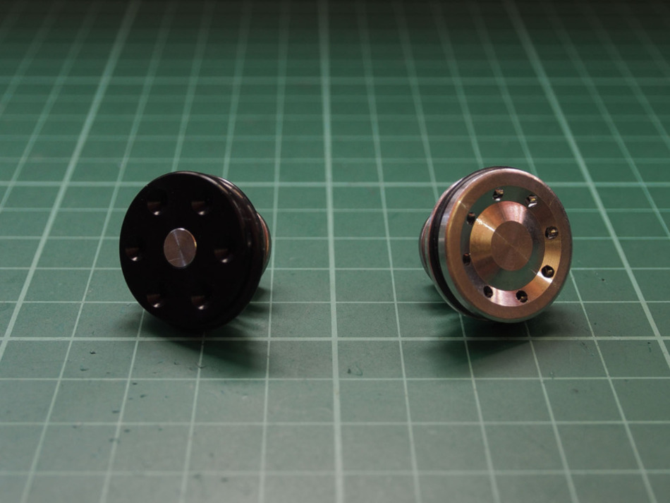
The piston I purchased actually came with an aluminum piston head, but I decided I’d be using a Lonex POM (Polyoxymethylene) piston head which is made of a sort of tough low friction plastic which is lighter and less likely to scratch the cylinder walls.
Adjustments
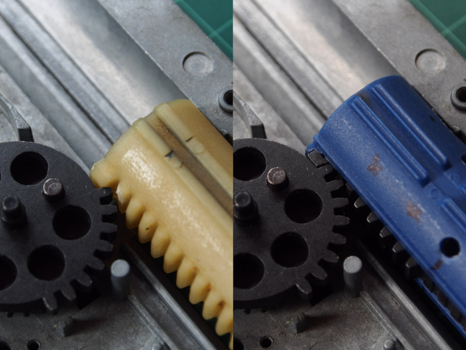
The piston body I’m working with is an SHS 16 tooth polymer piston (not entirely sure what it’s made of). The tooth rack is metal and can be separated from the piston body. Despite being metal, the design of the pick up tooth, the first tooth on the rack that the sector gear interacts with, and where it sits on the piston worries me. It might just be a quality control issue, but the material looks thin and it doesn’t sit flush.
For our purposes, the sector gear we have will only pull along eight teeth on the piston’s rack before releasing the piston assembly to complete a single compression stroke.
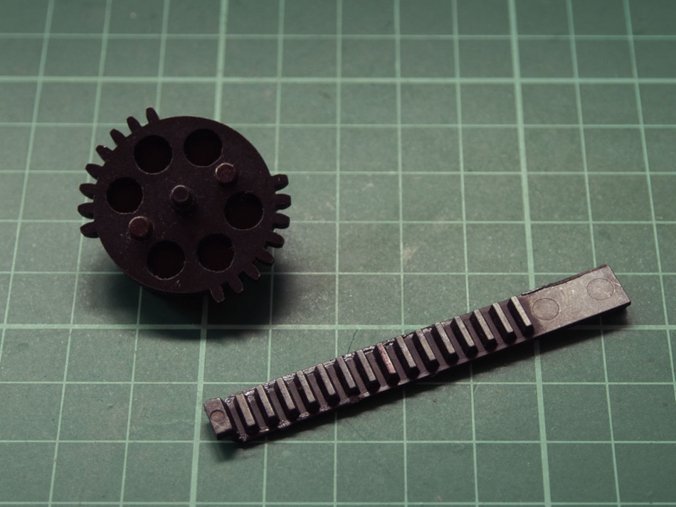
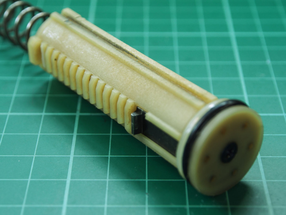
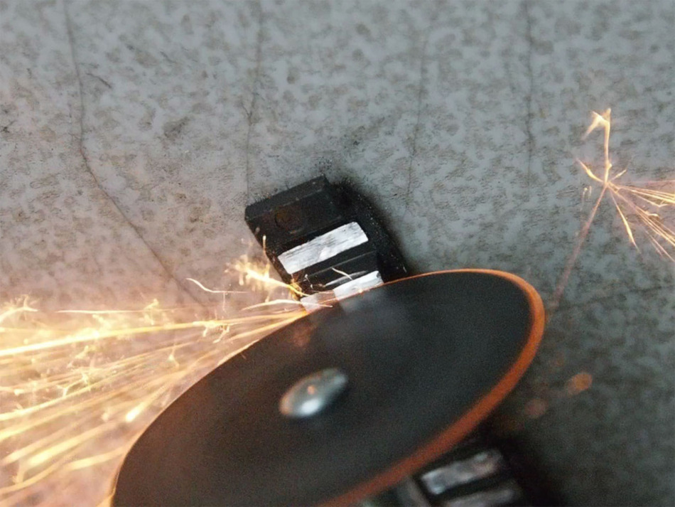
Because the piston is released on the eighth tooth I do not need the other eight so I shave the excess teeth with a dremel tool and a small cut off wheel, starting from the furthest end at which a sixteen toothed sector gear would have released the piston.
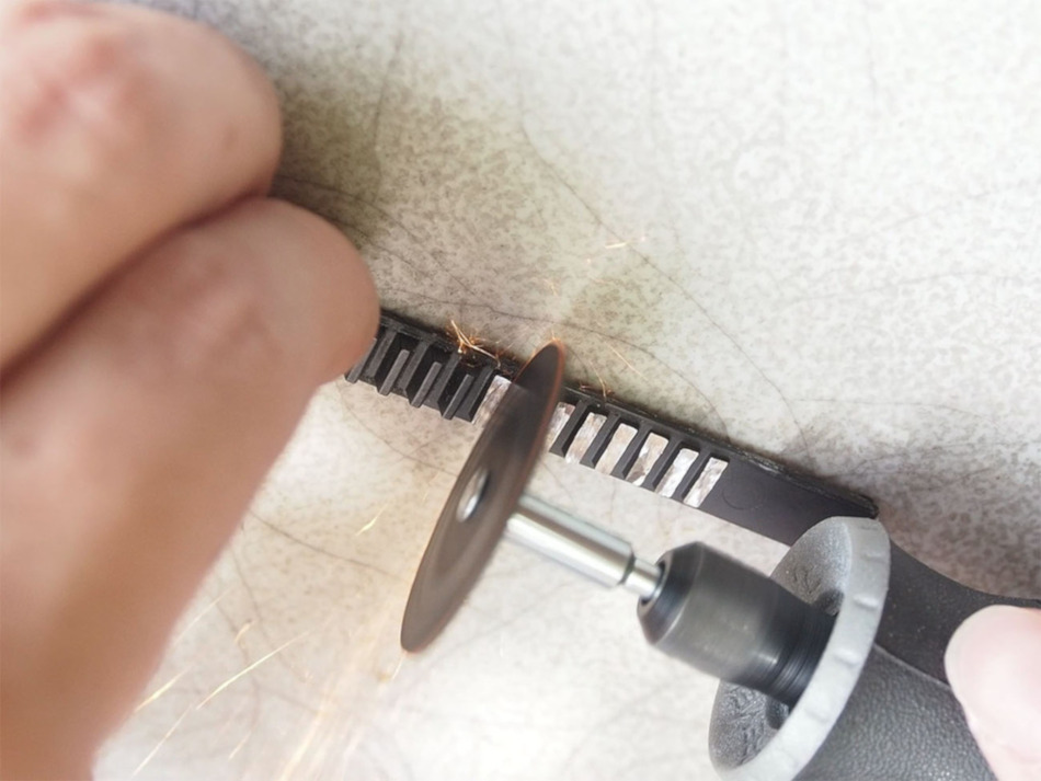
More shaving is done on the top end of the rack so that the head is able to sit flush with the piston body. This step may just be a result of quality control issues with the piston I got and not a necessary step for all piston bodies.
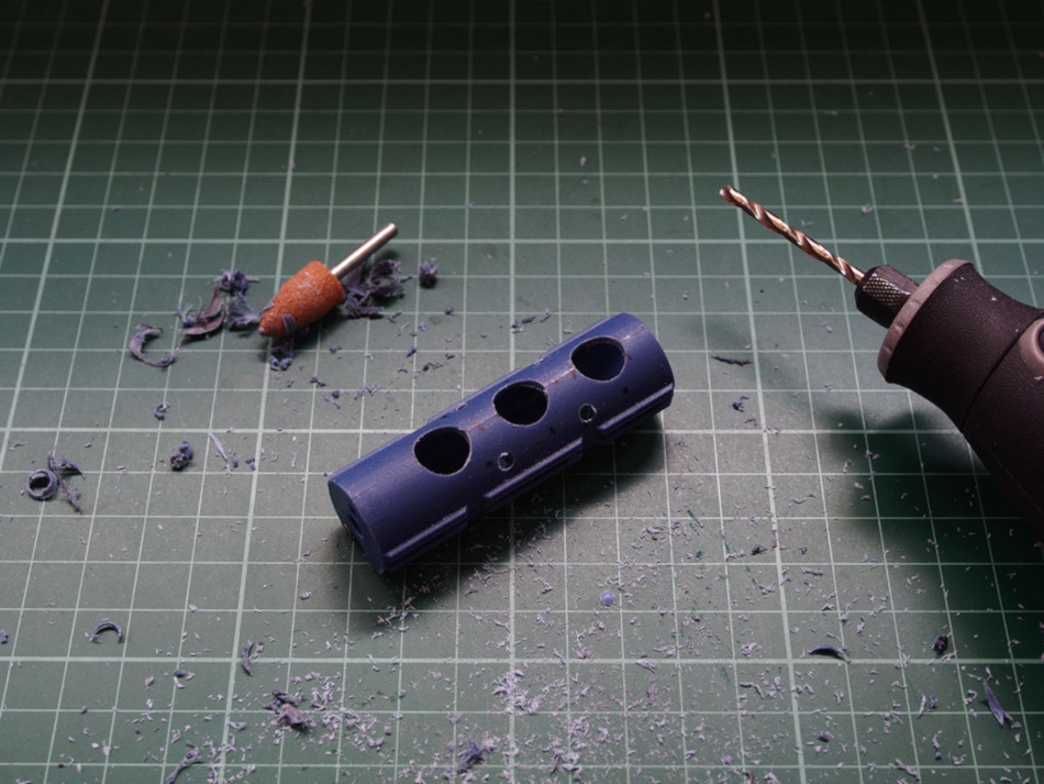
I will also be lightening the piston assembly by drilling holes into it and not including the bearing on the head. The process of drilling holes onto the piston is called “Swiss Cheesing” or just Swiss Cheese. Its primary purpose is to lighten the piston in hopes of increasing rate of fire.
This practice has been around for a long time. Older even than my G3. Sadly I could not find the originator of this technique that introduced it to the airsoft world. Perhaps its roots can be traced back to the automotive industry.
Furthermore there were debates on the piston’s structural integrity after this mod is applied, but so far has proven itself to be sound. I only put a few holes onto our SHS piston to account for the high powered spring that will be used for this project.
On top of swiss cheesing, the thrust bearing that came with the piston head will be removed to reduce overall weight even further. A spring guide with bearing will be sourced so the spring twist will not be much of an issue. In exchange we will lose some muzzle velocity by removing the bearing on the piston as that would have counted for loss in additional spring tension, a sound compromise to reduce mass.
For our purposes, reducing piston assembly’s mass is not so much for the purposes of increasing rate of fire as to hopefully mitigate some of the impact forces experienced by our gearbox.
This is because the version 2 gearbox shell we are working with is known to have a vulnerable front end and is prone to cracking or total failure compared to other variants. Other versions like the version 3 gearbox shells found on the AK, G36, and even the TM MP5K-H v1.0 variants are less likely to break, but as a sort of “best practice” habit it would be wise to take similar precautions.
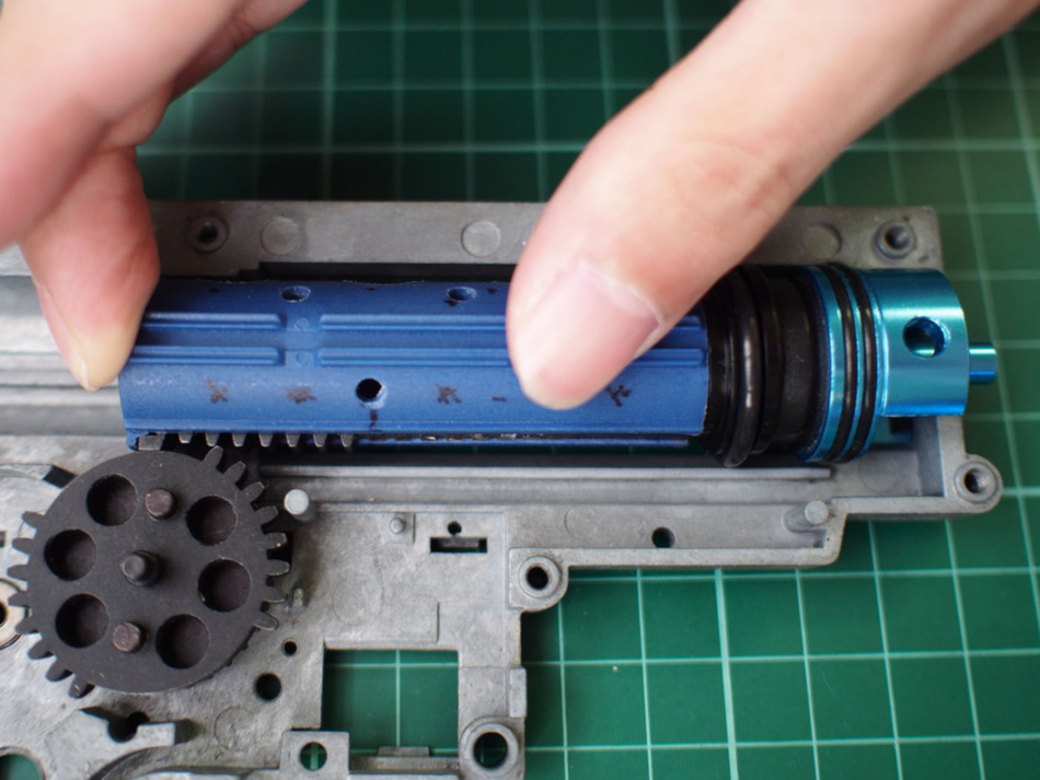
Next up is the piston’s resistance. One other thing you should check is the piston body’s fit in the gearbox’s guide rails. Move the piston body along the railing and feel for any resistance. You will want the piston body to drop into the rails under it’s own weight and move along without any drag.
The fit here seems to be quite tight. The rails on the piston itself extend out more than necessary by a very small amount, but enough to prevent free movement. They will have to be shaved down.
Further Tuning: AOE
I should take this time to talk about Angle of Engagement, or AOE, because setting AOE dictates how much of the teeth near the pick up tooth end of the rack is to be shaved down, if any. The forums at AirsoftMechanics.com has a good thread discussion about this topic.
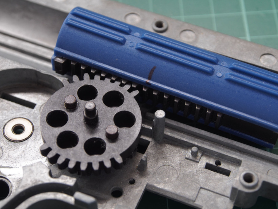
AOE refers to the angle at which the sector gear contacts the pick up tooth of the piston assembly. In an unmodified AEG, it is common for the face of the sector gear tooth to attack the edge of the pick up tooth on a piston instead of it’s face. It is believed to have sub-optimal mechanical advantage and results in an unnecessary excessive upward vector force which can cause the piston to break.
Too much or too little adjustment in AOE leads to “edge-on-face contact” wherein the edge of a tooth, be it the piston’s or sector’s tooth, will contact with a sharp edge directing force at a single point instead of spreading it over a larger area.
You can adjust AOE two ways; one by using washers or spacers between the piston head and piston body to adjust the length of the piston assembly, and the other by installing material on the cylinder head, commonly a Sorbothane pad, to shift the whole piston assembly.
Correcting AOE prolongs piston life and is done by attempting to get the face of the first sector gear tooth to contact as much surface area on the face of a piston’s pick up tooth at the start of the stroke. This adjustment avoids destructive “edge-on-face” contact between the interfacing teeth, and at the same time, reduces the upward vector force the piston experiences when the sector tooth contacts the piston’s pick up tooth.
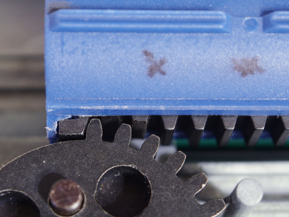
In the example below introduction of the shock absorbing pad between the cylinder head and piston head sets the correct angle of engagement between the piston’s pick up tooth and the sector gear’s initial tooth. Details on the shock absorbing pad will be covered in a later entry. It’s purpose in this stage is to correct for AOE and determine the adjustment to the piston’s teeth.
In this setup, the sector gear spins back to pull at the piston, but the gear teeth become obstructed by the second and first tooth after the “pick up tooth” on the piston assembly on account of the new position introduced by the shock absorbent pad. You want the sector gear to contact the piston’s “pick up tooth” first. Leaving this as is will result in broken inconsistent operation and ultimately damaged piston or gear teeth.
The solution is to trim just enough on the second tooth after the pick up tooth to allow the sector teeth to pass, but leave material for the sector to get some leverage as it pulls along the rack. Avoid completely removing the third tooth as it will place excess stress on the pickup tooth and the first sector gear tooth during operation. In contrast, the second tooth on the rack at the pick up side needs to be shaved down all the way.
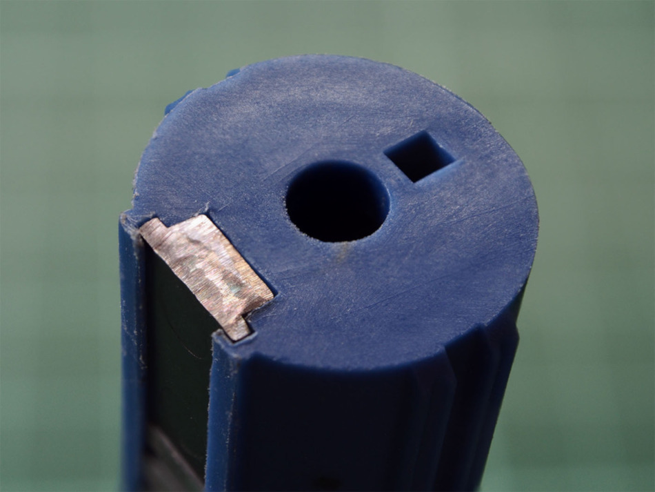
Here is the piston tooth rack after accounting for both AOE and the 8 tooth stroke. Notice how the two teeth to the left side, or pick up end, are shaved at different heights.
Fitment reveals that we are close enough to the correct angle of engagement which prevents edge-on-face contact between the first piston and gear teeth.
Summary
For this particular build we are using a Lonex flat faced POM piston head in combination with a SHS piston body with removable full length metal tooth rack. The flat piston head face makes it easy to make use of the shock absorbent pad and cylinder head type I had on hand.
Lightening of the piston assembly was done by drilling holes in spots I thought wouldn’t compromise structural integrity, and the thrust bearing that came with the piston head was removed. This was all done to reduce the impact force of the piston assembly slamming onto the cylinder head and gearbox front end.
Resistance between piston and gearbox is checked, and the piston or gearbox rails are shaved or polished until the piston can move freely under it’s own weight.
We shaved off the last eight of the sixteen teeth on the rack because I was using a dual sector gear that only contacts eight teeth per piston stroke. The number of teeth you shave is dependent on the number of teeth you plan to use on the sector gear for your particular application.
After test fitting the piston for corrected angle of engagement, I shaved down the first tooth after the pick up tooth on the piston body completely and part of the second tooth to allow the sector teeth to clear and operate unhampered.
Ports on the piston head are checked for any clogging, and during final assembly, you will want to use epoxy or super glue to lock down the tooth rack to the piston body and a dab of removable thread locker to keep the piston head from coming undone.
This marks completion of the work done on the piston assembly and first core component of our AEG internals. Depending on your goals you may end up with a completely different variation, but the process of selecting parts and adjustments for fitment should remain the same.
When I started this post I didn’t think there would be so much to cover with just the piston assembly. There is probably more to be said, but things covered thus far should be sufficient for most situations.
So like the warriors that we are let’s push on with the build, and in the next entry for this series we will be tackling the cylinder assembly and matching the inner barrel.
– J4
