The cylinder assembly is the second half of the compression component in an airsoft automatic electric gun, the other half being the piston assembly.
Together, they work as a pneumatic system that serve the function of transferring force from a spring to propel projectiles called bbs through a barrel.
The cylinder assembly is one of the easier parts to put together. Most aftermarket vendors will label each piece for compatibility. Despite this, upgrading an Airsoft AEG is rarely as simple as picking out components, and there are still key points to keep in mind to maximize fps gains and prevent feeding problems.
For those who want a more visual experience, I cover the adjustments and modifications to the cylinder set in the following video. However a lot of the details and reasoning is left out, so I highly recommend that you still read through this entry to better grasp the idea behind the actions carried out.
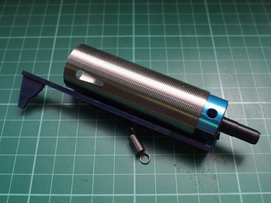
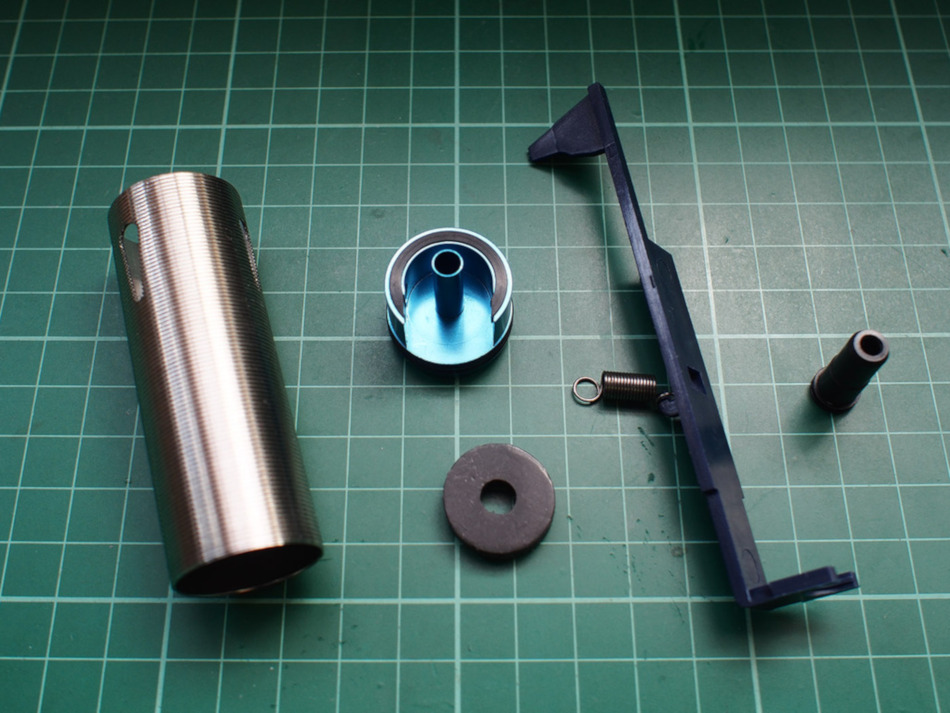
The cylinder assembly is mainly composed of the cylinder head and cylinder. However, aiding in the loading of bbs into the hop chamber and transfer of air into the inner barrel, we have the the air seal nozzle and tappet plate. During installation of the cylinder assembly, these 4 parts are installed together as one unit.
Cylinder Head Preparation
There are different versions of cylinder heads for different gearbox versions. Depending on the AEG model, it can have different variations of gearboxes.
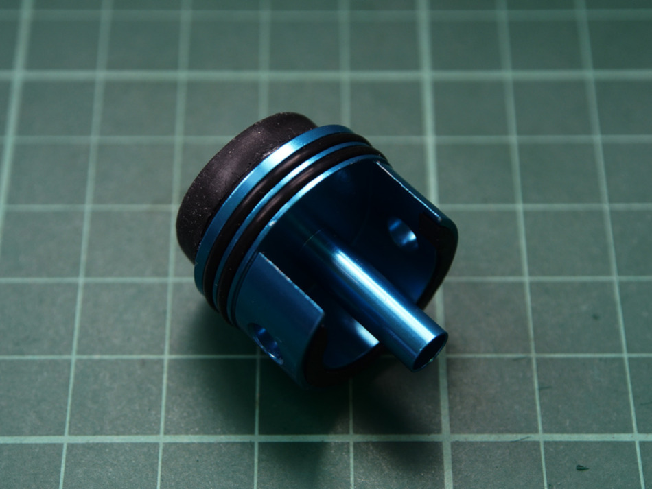
The TM G3 uses a version two gearbox so we have to use a version two cylinder head as well.
Stock AEGs will usually come with a polymer cylinder head. I find them to be quite durable, but may crack eventually when using a heavy spring. Aftermarket ones are usually a sort of alloy or metal like brass and can have a different number of o-rings to make sealing easier.
The impact material at the back comes in different configurations. Flat, concave, or a mixture called tapered. The concave shaped rear is more common with cylinder heads designed for bore-up sets which use mushroom shaped piston heads now referred to as silent piston heads.
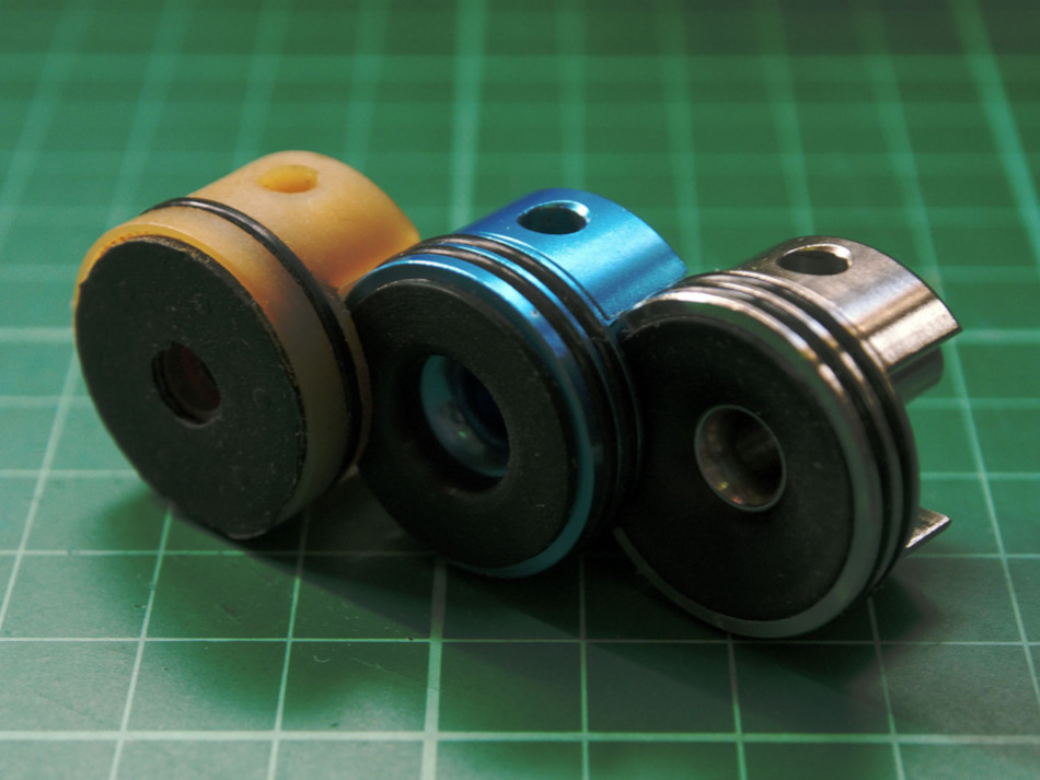
Choosing the right cylinder head is more about what version gearbox your aeg is using and less about performance gains. I have found that single o-rings can seal just as well as double o-rings and the flat impact material is easier to work with when installing sorbothane pads.
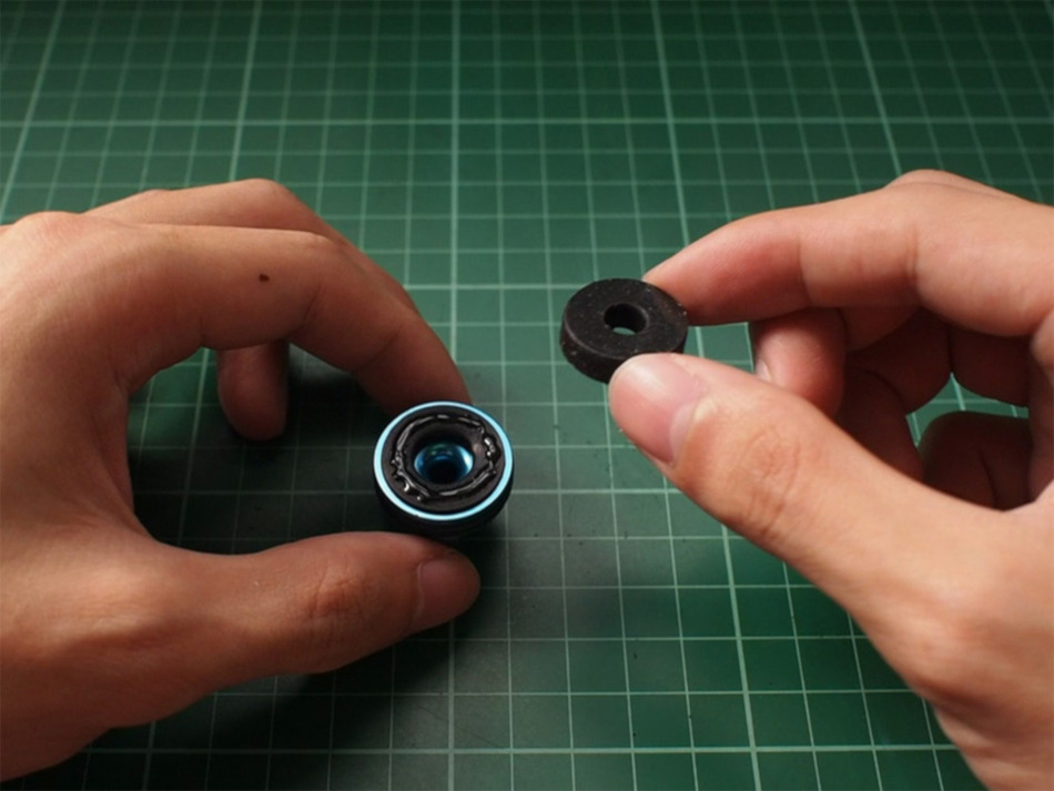
Installing a Sorbothane Pad
Sorbothane is a very good shock absorbent material that will help us reduce stress on the gearbox from the piston’s impact. They can be bought pre-cut or in sheets and come in different stiffness ratings called duro. We are using a stiffer 70 duro pre-cut pad that’s 3/16″ in thickness, from here, that’s less likely to deform and change our angle of engagement (discussed in P1 – Piston Preparation).
Despite the Lonex having less surface area for the Sorbothane pad, we will still be using this over the stock Chinese clone to observe how the pocket created by the uneven contact patch affects performance and durability. In the worst case scenario, I expect the pocket to create back pressure against the Sorbothane pad as the piston pushes air through the cylinder head, eventually leading to the Sorbothane pad’s removal.
Scatterplot has released a new version for use with Lonex cylinder head since my last purchase that fit better which they refer to as tapered v2/v3 pads.
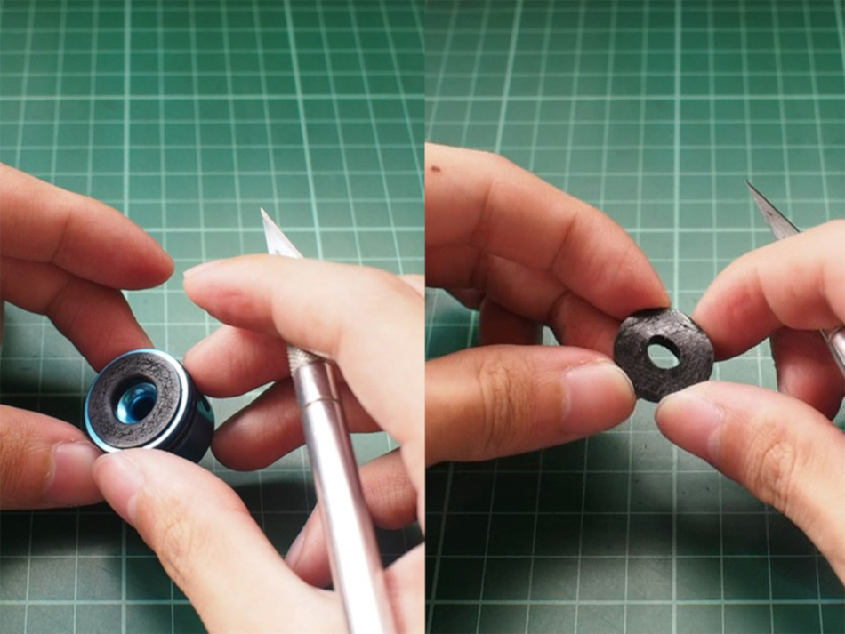
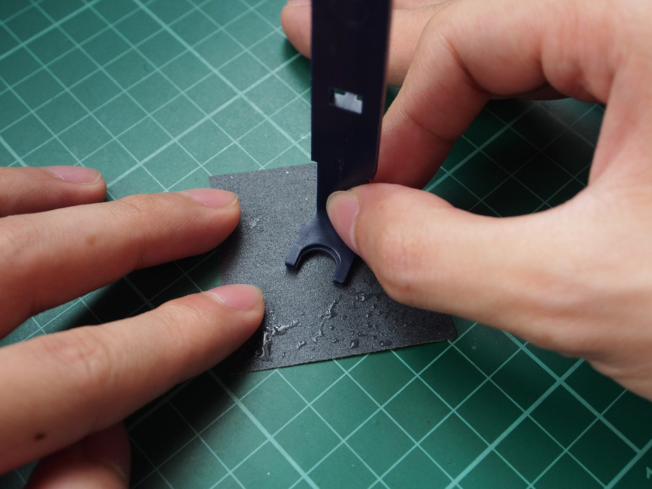
Moving forward, the first thing we have to do is prepare the cylinder head by roughening up the surface of the impact material behind the cylinder head. We will do the same thing on one side of the Sorbothane pad and then stick these scored surfaces together using superglue while being careful that the holes of the pad and cylinder head line up properly.
Another way to do this is to remove the existing impact material, score the cylinder head, then apply the Sorbothane pad directly. However, since we are using the Sorbothane pad to correct for AOE as well as shock mitigation, we will not remove the existing impact material.
Cylinder Type
The cylinder acts a reservoir that holds the air which will be used to propel bbs. There are designated cylinder types that hold different amounts of air volume. You can identify them by type and the change in the air volume is determined by the positioning of a port, or ports, on the cylinder walls. These ports also maximize the spring’s potential by allowing the piston assembly to accelerate further past the port’s location before compression slows it down.
Typically the choice of cylinder is a matter of picking out a cylinder type which manufacturers have identified and approximate works with your AEG or barrel length. These days barrel length is predominantly the determining factor as manufacturers have realized that modded AEGs can come in various different lengths.
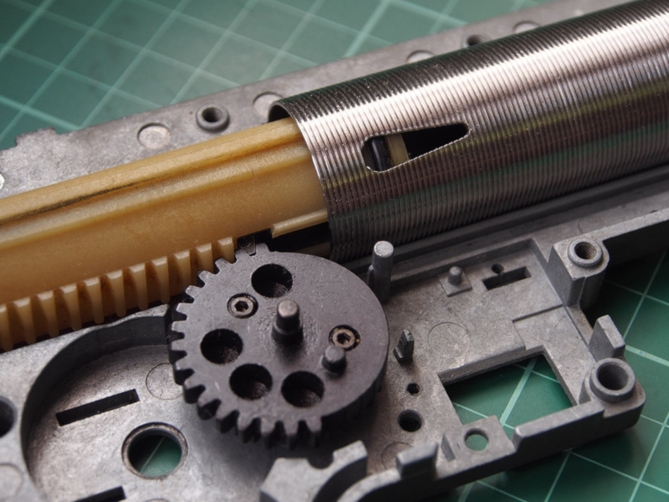
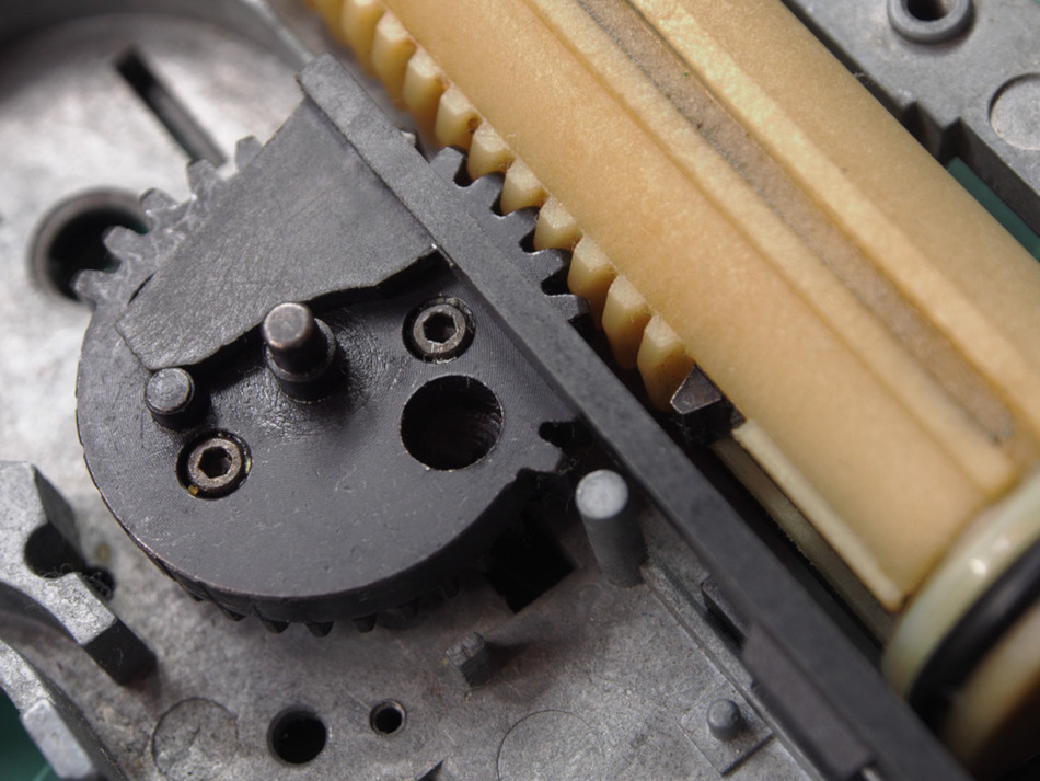
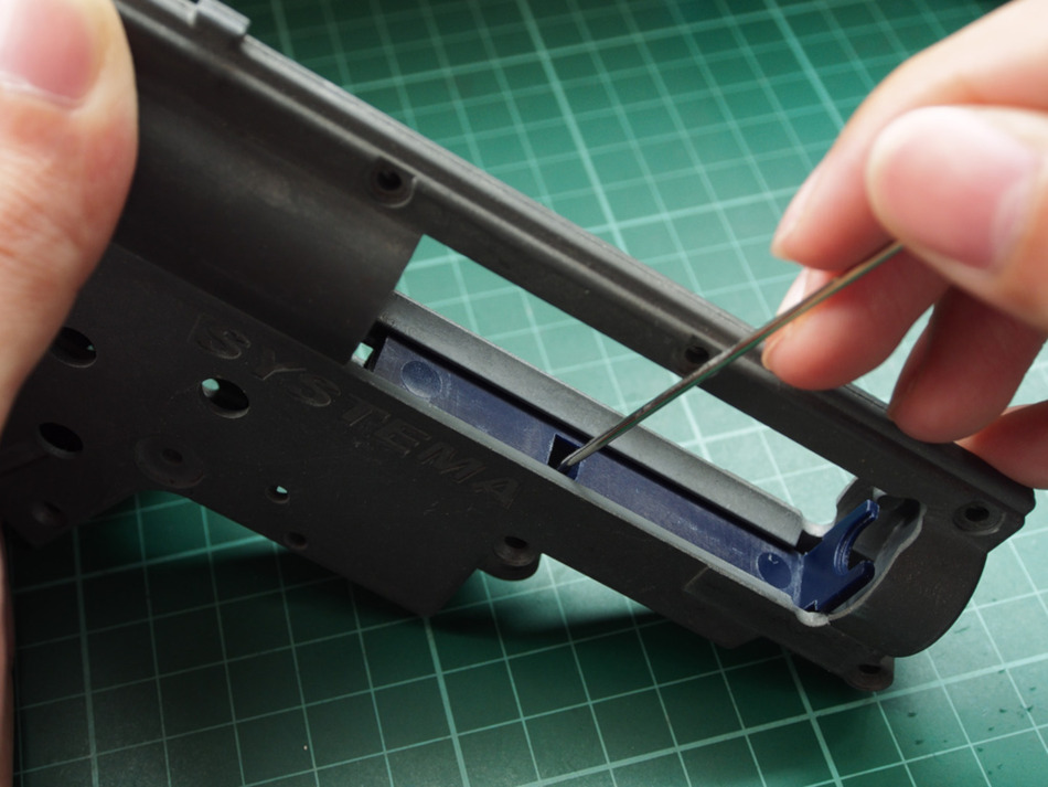
Using a ported cylinder as an example, a sector gear with 16 teeth and a matching piston without alterations will shift back enough for the piston head to clear the ports as shown below.
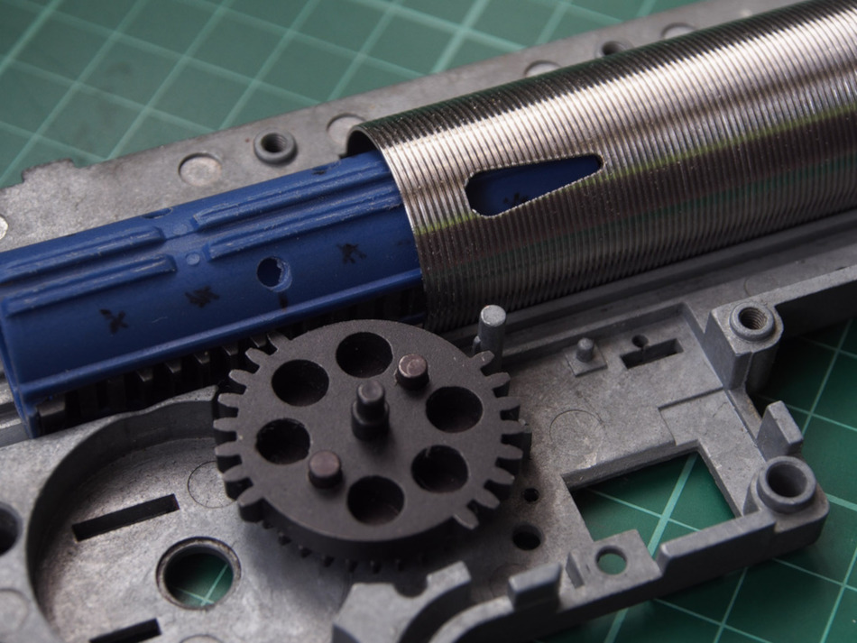
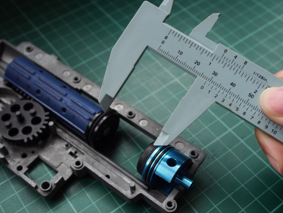
In comparison, the following image shows the configuration using the same ported cylinder using our modded piston and G&G’s take on the dual sector gear.
The idea behind the ports is that, depending on barrel length, you may not need the full volume of air provided by a cylinder without ports. By placing vents for air to escape compression is delayed until it’s needed allowing the piston to accelerate further improving efficiency in the spring’s transfer of power. The closer the port’s location to the rear end of a cylinder the more air volume it can provide for longer barrels. Ports further at the front have limited air volume and are used for short inner barrels.
In our case, the short travel of our piston does not allow the piston head to make use of the ports. Despite the ports playing no factor in our build, the short travel still translates to a lower volume of air because we are effectively limited to a fraction of the cylinder’s total capacity.
What this means for our build is that we are limited to running short barrels. In the end this may affect our maximum range and the possible aesthetics of our AEG.
A possible solution is to adopt a bore-up cylinder and cylinder head. As the name implies it is a cylinder with a slightly wider inner diameter originally used to provide more air volume to propel bbs through inner barrels above 550mm in length.
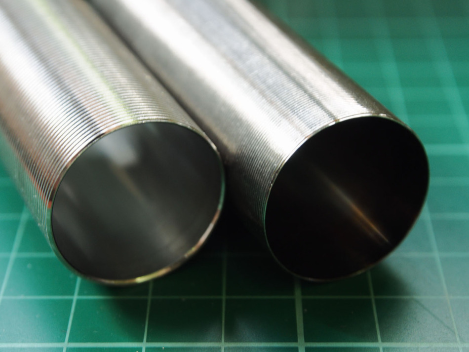
The diameter difference between the two cylinders above is about 1.3 millimeters. It’s 24.9 millimeters for the bore-up cylinder versus 23.6 millimeters for the standard one. A 1.3 millimeter difference might seem small, but when calculated, it translates to about an 11.32% air volume gain over the non-bore-up cylinder!
Volume Matching
Ideally you will want your bbs to exit the inner barrel just before the piston head makes contact with the cylinder head. Too soon means you have an over volume and the piston head will hit the cylinder head with extra unneeded force and produce a loud sound signature.
In addition the extra air from the excess cylinder volume may cause turbulence behind the bb after it exits the inner barrel that could disturb it’s flight path, affecting accuracy. Too late and you may not reach the spring’s intended velocity rating leading to poor FPS readings.
By getting measurements and using the equation πr²*H, where r is the cylinder’s radius and H is the piston head’s travel, you can calculate the air volume your system makes. Likewise you can use the same equation and substitute r for the radius of the inner barrel bore, and H with the length of the inner barrel past the hop window and towards the end where the bbs exit.
With light bbs, 0.20g to 0.25g, you will want to maintain a ratio of 1.5 cylinder air volume to 1.0 of the barrel. In a perfect world it would be one to one, but in real life we have to account for drag caused by friction and mass. For bbs past 0.25g you will need more air volume to overcome drag.
When using wide bore barrels you will also need to account for blow-by caused by the increased gap between the bb and the barrel walls which allow more air to escape, and therefore need to push the ratio even further.
The initial ratio we decide on is more of a guide. Getting the exact ratio for the application can be tricky and is largely trial and error wherein you need to use a chronograph and identify at which point the set up produces the highest fps readings. This is where tuning of the ports on a cylinder and the use of spacers come in.
For our build, we are already stripped for air volume due to the short stroke as shown above. With only 28.5mm of piston travel it equates to about 12,466.91 mm³ using the formula we discussed. Considering a ratio of 1.5 we need a barrel with a maximum volume of about 8,311.27 mm³. That leaves us with about a 286.41 mm or 286 mm barrel length with a 6.08 mm bore diameter to make use of if we consider bbs up to 0.25g.
Should we want more air volume to run heavier bbs or use a longer inner barrel, the only other upgrade we can apply is to use a bore up cylinder set. Running a tighter bore such as 6.04 mm as compared to 6.08 mm will net us about 4 mm more length at about 290.21 mm. A small difference in my opinion, but will lead to higher fps readings.
Tappet Plate
The tappet plate is a plastic arm with a fin that synchronizes the loading of bbs into the hop chamber with the cycle of the piston through a peg found on the sector gear. Depending on the fin design, the characteristics of feeding bbs into the hop chamber can be tuned.
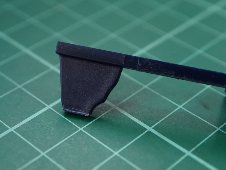
Siegetek Riot SC, the inventor of the dual sector gear suggests that the tappet plate fin be cut to size at 11mm long. I used a Sharpie here and the X-acto knife to scribe where I plan to cut.
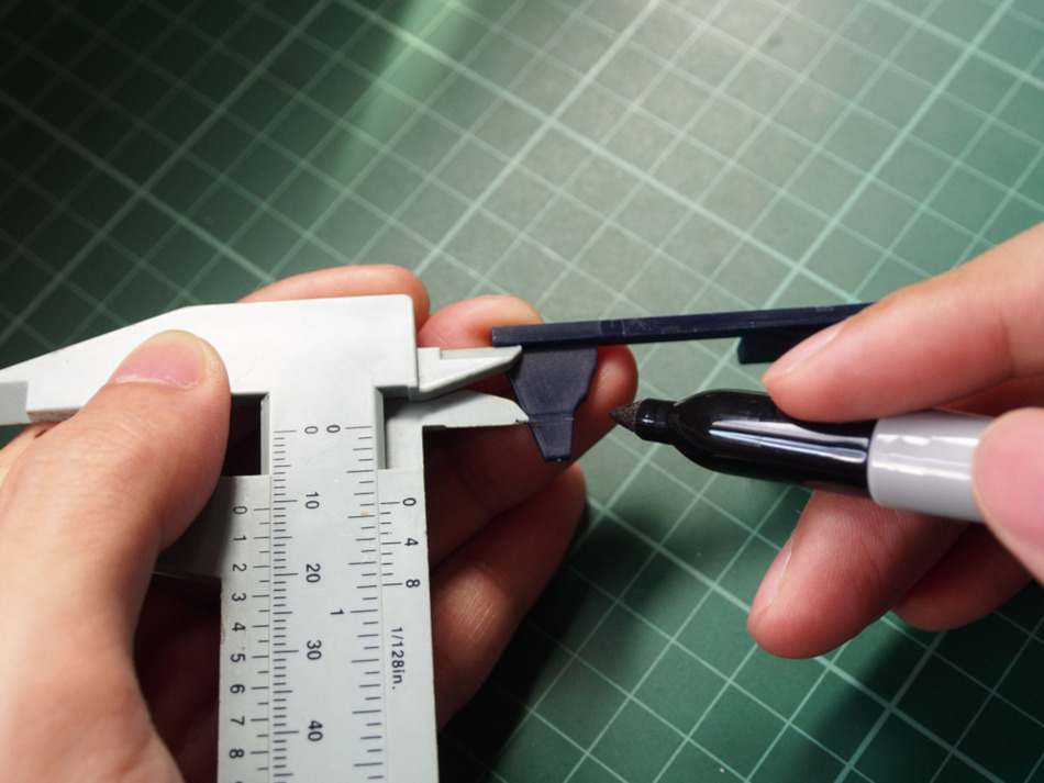
With the tappet plate fin measuring 11mm long the nozzle chambers a bb just before the sector gear releases the piston. I would have liked to cut just a bit more material off to speed up the actuation, but the window for bb’s to enter might become too short.
Compared to a full length fin the window for bbs to climb up into the chamber is shortened. With the nature of a dual sector gear build actuating the tappet plate twice as much per revolution compared to a conventional sector gear, that window is further decreased and may compromise feeding. Therefore the tappet plate needs to be drawn back for as long as possible to ensure that feeding issues are mitigated.
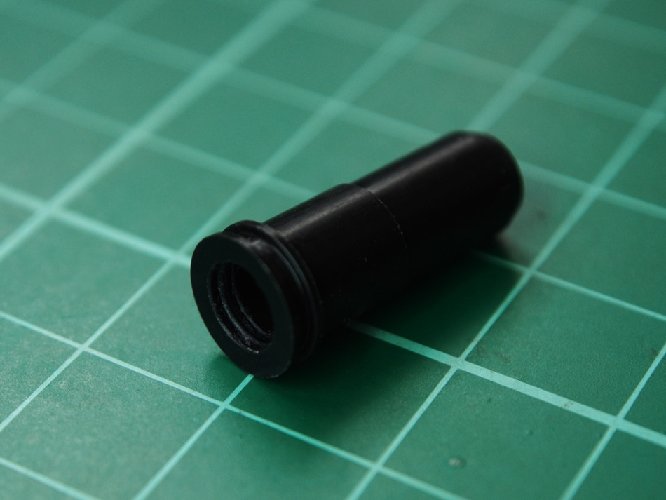
Air Seal Nozzle and FPS Gains
The air seal nozzle is a moving component that slides along the cylinder head’s tube. Together with the tappet plate they allows bbs to feed into the hop chamber without air escaping during the bb’s firing cycle.
After letting bb’s into the chamber the air seal nozzle pushes against a rubber hop bucking inside the hop chamber ensuring that the air transfer from the cylinder assembly is air tight.
Stock air seal nozzles usually have no o-rings and can be a source of air leaks causing drops in muzzle velocity. However o-rings can also be a source of drag in high speed set ups so it is important to keep them clean and lubed to minimize resistance.
As far as choosing an air seal nozzle is concerned, it is just about getting the proper length at which it does not impede feeding by being too long, but not too short either as to being unable to create a proper seal with the hop bucking found inside the hop chamber.
Usually the air seal nozzle is pre-measured and labeled for which model AEG it is designed to work with. Though sometimes tolerances can be loose enough that modding the tappet plate or a different air seal nozzle becomes necessary.
Another mod involves shaving the front of the tappet plate that rests on the gearbox shell to pull the air seal nozzle further into the hop chamber creating a better seal.
Summary
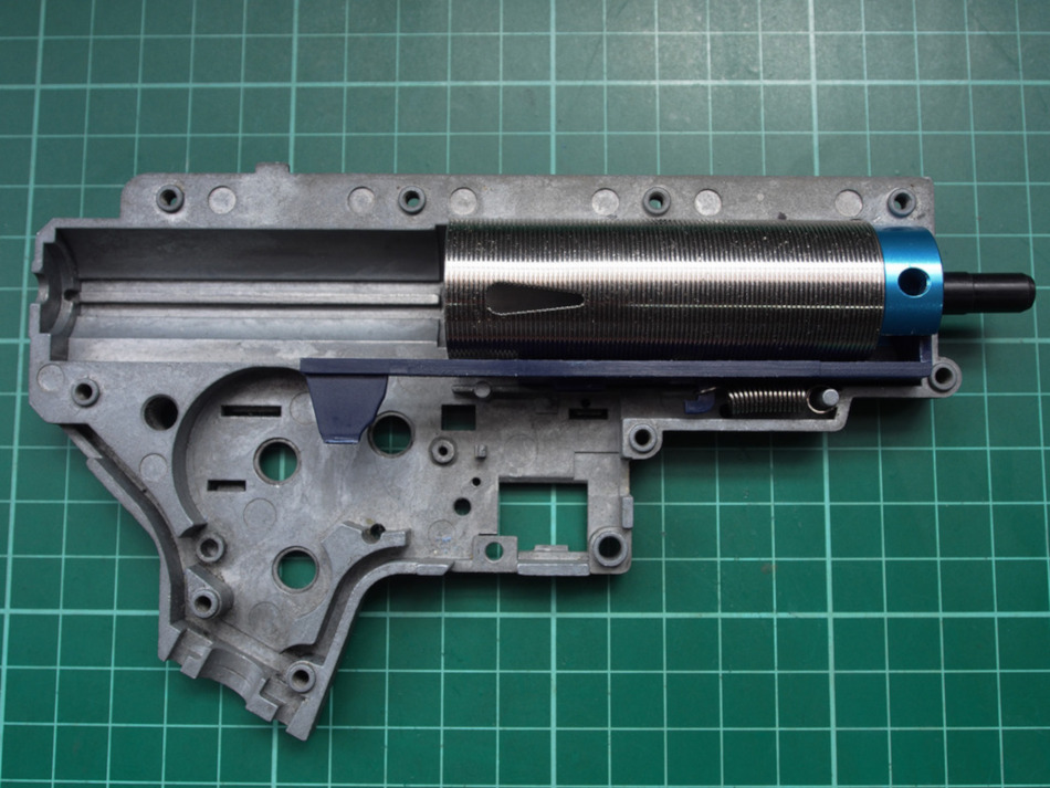
At this point it is time to put everything together. We can do a test fit and it should look like this.
So far, we’ve applied a Sorbothane pad on the version 2 cylinder head that serves to mitigate shock and correct for angle of engagement. There are different cylinder types for different barrel lengths, but in our case, the piston we put together predominantly dictated the barrel length for our build. We will be running bbs not heavier than 0.25g and therefore went with a ratio of 1.5 to 1, which lead us to a maximum barrel length of about 286 mm at a 6.08mm bore diameter.
The tappet plate was shaved down at front to improve sealing of the air seal nozzle with the hop bucking as to prevent air leaks during the pneumatic compression. Material was trimmed off of the fin until we got a length of about 11mm, which was the recommended length for compatibility with dual sector gears, as stated by Riot SC’s guidelines. Components were then cleaned out to minimize resistance between moving parts.
This build is my first foray into the world of dual sector gears and there’s no way to tell how the parts will perform as a whole just yet. But with the preparations we’ve made, I am highly optimistic and confident in the future result. If I had to guess, the area we might need to tweak more will most likely be the feeding characteristics of the tappet plate.
In conclusion, the key when working with the cylinder assembly is to match volumes to your requirements, ensure air tight seals, and prevent feeding issues by minimizing drag between moving parts.
Keep these three things in mind you’ll be able to naturally pinpoint the areas that need your attention, and be on your way to assembling great performing cylinder sets, the warrior way!
Next up for this build is gearbox shell preparation.
– J4
