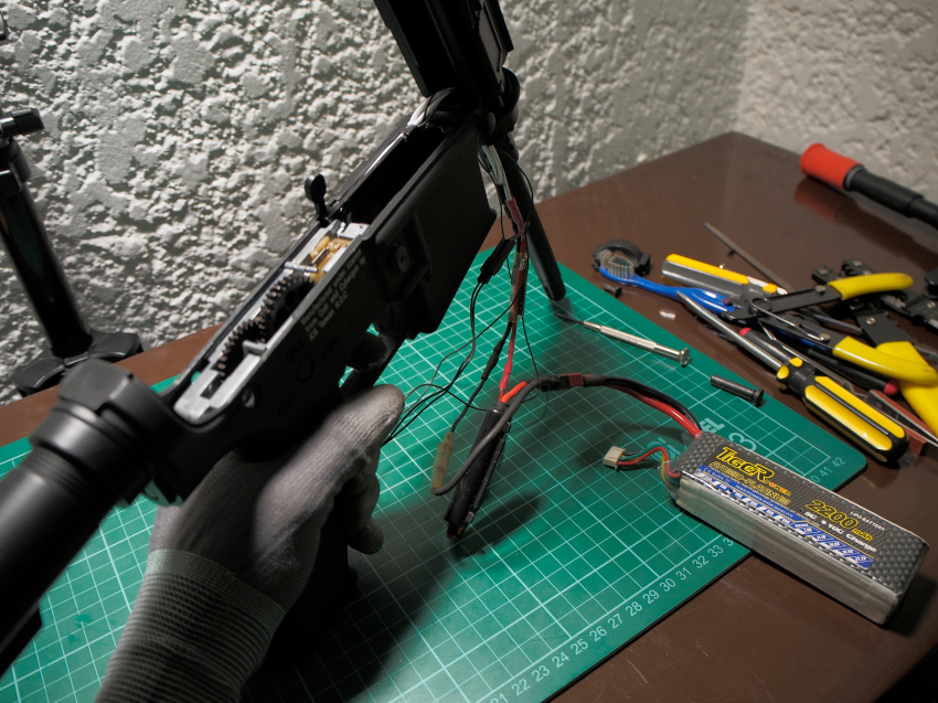
A few days ago I finally posted my video on the installation of a Metal Oxide Semiconductor Field-Effect Transistor, or MOSFET, into an ICS M4 airsoft gun. This formed part of the rewiring process required to improve and protect the stock airsoft trigger circuit. The desire for higher levels of performance has seen the widespread adoption of 11.1 Volt LiPoly batteries, and the accelerated damage caused by electrical arcing on the trigger contacts. Therefore, the use of MOSFETs in today’s age of high performance automatic electric guns has become mandatory.
We know that the main function of MOSFETS in airsoft is to prevent arcing, but how does it do this? First, you have to look into what causes arcing.
What is an Electrical Arc?
A quick google tells me that electrical arcing happens when an electric current flows through the air between two conductors. The air undergoes an electrical breakdown and produces light.
Electrical arcs result in very high temperature and are capable of melting or vaporizing most materials. These qualities have found industrial applications in the form of welding and plasma cutting.
Why it’s bad and what to do
Imagine these high heat principles at work in an airsoft gun. Airsoft guns that run on batteries have trigger switches. Each trigger pull has the potential to cause arcs that will eventually eat away at the contacts. If not remedied, you will end up with a non-functioning trigger switch and inoperable airsoft gun.
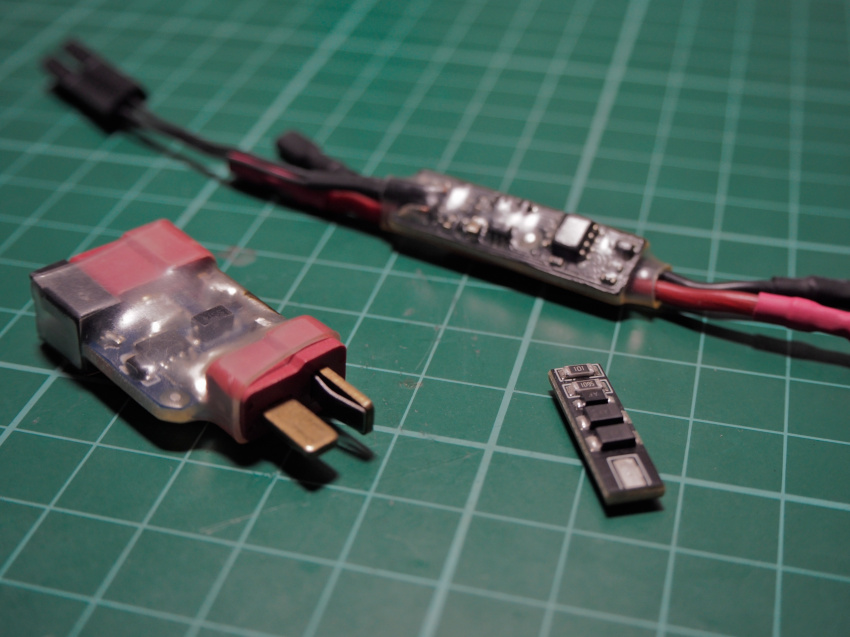
This is where the MOSFET comes in. The airsoft gun is rewired in such a way that it eliminates the need for electricity to cross through the air. Because of this, adding a MOSFET to the circuit establishes a very stable path for charge particles to run through. For more on MOSFETs please visit the resource page.
Problems with the Trigger Switch
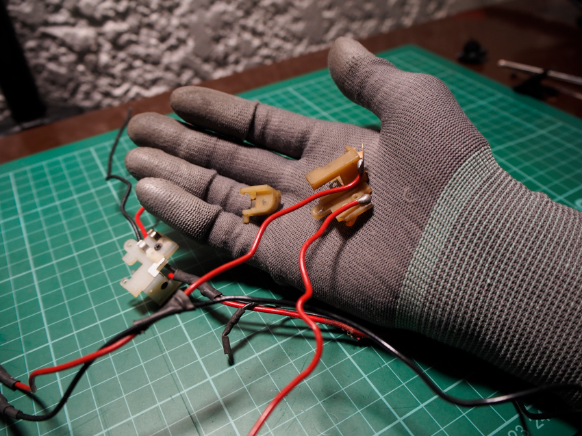
This AEG is actually a part out from a friend and client. There were two of these I Chih Shivan (ICS) M4s and we had used one as a donor to repair the problems we encountered on the other. One of the problems was that of a faulty trigger switch that the cut off lever could not actuate. Therefore, our solution was to transfer the switch from one to the other, which we did. Because of this, the faulty trigger switch remained with the donor AEG that I am working on in this restoration.
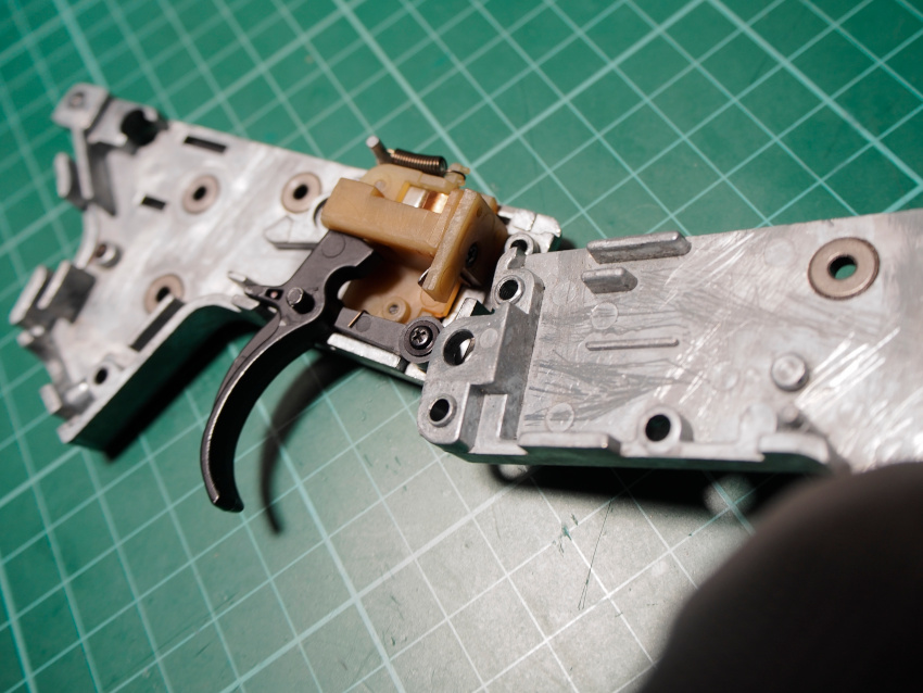
My solution to this problem was to get another trigger switch and convert it to fit. The typical off the shelf version 2 airsoft trigger switch will not fit int an ICS version 2 split gearbox. Some slight modifications are necessary for it to fit.
Rewiring the Airsoft Gun
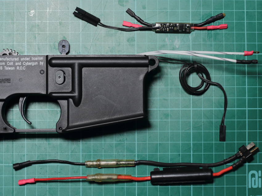
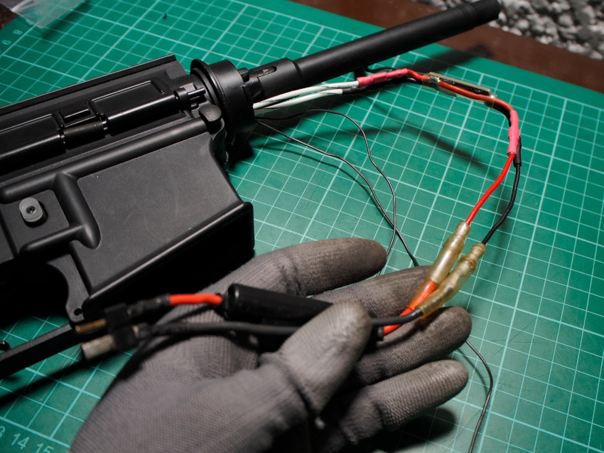
I use GATE Electronic MOSFETS for their size that makes them easy to fit almost anywhere. A good example of this is the slim Pico AAB that is not only compact but also featured rich. Installing the PICO AAB for the best results involves rewiring the circuit and I decided to run new wires that were a thicker wire gauge in hopes of improving the electrical flow.
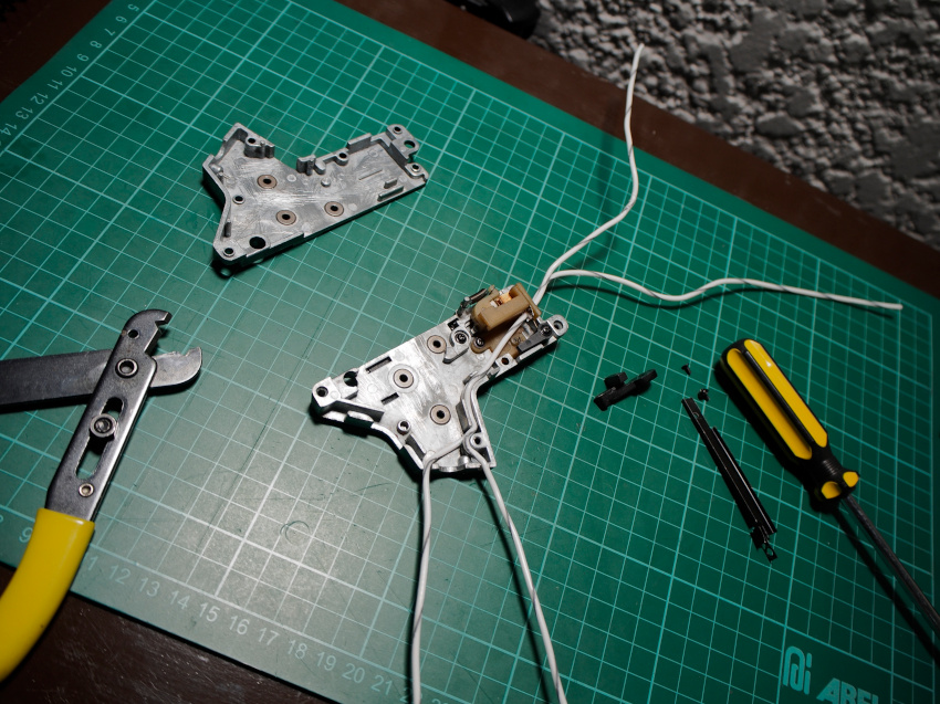
Traditionally, the trigger switch would bridge the contacts and power would run through them. Instead, I have the wires run straight from the motor to the MOSFET and power source. The triggers no longer have to have current run through them. Instead, the trigger switch is now what sends the voltage signal to the Gate channel on the MOSFET that drops the resistance to allow charge carriers through.
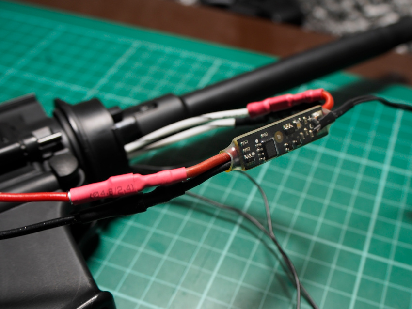
I also included a fuse holder at the battery connector end. Gate Electronics states that they have electronic fuses built into their MOSFETS, but still recommends the addition of fuses in the AEG circuit. I’ve run through my fair share of MOSFETs that would malfunction due to short circuits, so adding a fuse will help as an additional fail safe.
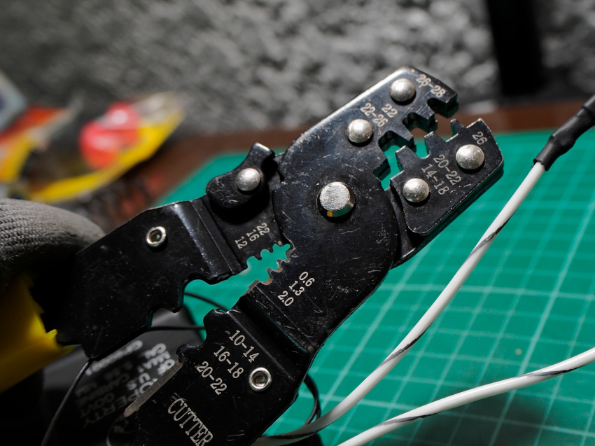
Pro Tip: I highly advise that a good crimping tool is sourced. Mine was horrible to use and had loosely riveted jaws that made it a challenge to make any good crimps. I just made it work to the best of my abilities with extra unnecessary effort.
Results
Switching out the trigger switch resulted in consistent contact between the cut off lever. Because of this, it began to function properly and resulted in the repair of the faulty semi-auto function.
The Gate PICO AAB MOSFET that was installed, also features an active breaking function that greatly reduced the over spin on the gears. Combined with the MOSFET’s more robust connection and quick switching, it resulted in quick and concise gear cycles.
For a more detailed comparison, please take a look at the before and after difference in the video linked at the top of this page.
Closing
Heya there readers! Firstly, I want to thank you for being here. In case you didn’t know, the Hobby & Tech Warrior website is a dear personal project of mine and is something I hope to have the pleasure of sharing with readers who find its content valuable far into the future. As it stands right now, this website is taking a lot of effort to keep updated.
If you found the information here valuable and would like to help in the maintenance of this endeavor, I’ve set up a tipping page you can check out to give direct support. Otherwise sharing these articles to your friends and social channels also goes a long way. Thank you in advance and I really appreciate your kindness.

That’ll be it for Part 2 of the ICS M4 rebuild. The trigger circuit has now been reconstructed and is ready for the next phase of the project. Let me know what kind of MOSFETS you are running on your own set ups. Check out the blog section for more articles like this one, and watch out for Part 3 of this series of articles which will be coming out soon!
Cheers!
– J4

